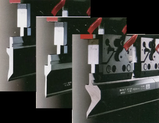
Do not select a V-opening from thickness alone. Check the complete geometry and load limits, then validate the tooling and blank definition together.
Planning guidance for buyers and trained teams. Follow the supplied machine and tooling manuals, approved procedures and safeguarding requirements. This is not an operating or commissioning manual.
Understand what the V-opening changes
Press brake V-die opening selection connects the drawing to the forming setup. Choosing a tool only because it is already in the rack can leave other requirements unresolved: the desired radius, the shortest flange, the finish and the available capacity.
In air bending, the sheet is not pressed fully against the die walls. The resulting process depends on the tools, material and required geometry. Bottom bending is a different method; an air-bending estimate should not be reused as approval for it. TRUMPF’s bending-method overview distinguishes these processes.
Before comparing tooling, state which forming method is intended. The same drawing can lead to different discussions when a critical radius or material requirement rules out a proposed process.
Review the radius and shortest flange together
WILA’s short-flange guidance notes that the minimum achievable flange depends on the die opening and shoulder radius. It also warns that selecting a smaller opening can change the inside radius and flat pattern while increasing required tonnage and other tooling concerns. See the short-flange application guidance.
That is why “use a smaller V” is not a complete answer to a short flange. The tooling specialist needs the whole drawing, material and permitted radius—not just one dimension. For some applications a different tool design or an engineering change may be appropriate.
| Requirement | Question to resolve |
|---|---|
| Inside radius | What radius is required, and how will the proposed process achieve it? |
| Shortest flange | Can the workpiece be supported by the proposed die geometry throughout the approved bend? |
| Return flanges and box depth | Will the complete sequence clear the punch, holders, machine and already formed features? |
| Holes and cut-outs | Does the geometry near the bend need a special tooling or design review? |
| Visible finish | What marking is acceptable, and what protection or tool choice is proposed? |
Check the complete load path
The machine’s headline tonnage is only one part of a tooling decision. Ask for the proposed forming load and the relevant limits of the punch, die, holders, clamps and machine configuration. Record the units and the loaded length; do not treat a force-per-length value as though it were a total force.
Use a manufacturer’s chart for its stated material, method and tooling assumptions. If the job falls outside those assumptions, request an application calculation rather than stretching the chart. A preliminary result from our bending calculator is a discussion aid, not a tooling approval.
Have off-centre loading, segmented tooling or other non-standard arrangements reviewed specifically. Do not assume that a tool used successfully on one machine remains suitable in a different holder or arrangement. Installation and operation must follow the applicable machine and tooling instructions.
Keep the cutting and bending definitions connected
When a tooling decision changes the agreed bend geometry or blank development, send the approved revision back to the cutting stage. A clean laser-cut blank is not necessarily the correct blank for a revised bending process.
Consider a hypothetical enclosure whose short return flange prompts a tooling change. Before production is released, engineering should resolve the formed geometry, blank revision and inspection requirements together. This example is a planning scenario—not evidence that a particular tool can form the enclosure.
Wavlon Lasers supports the cutting side of the partner ecosystem, while BENDRYX addresses bending. Share the same drawing revision and material description across both conversations. Our cutting-to-bending article explains the handover.
Bring your existing tools into the review
Existing tooling can be worth evaluating, but compatibility needs more than a photograph of the tang. Provide tool drawings or part numbers, working heights, interface dimensions, load ratings and condition information. Ask how adapters would affect the available opening and clearance.
Machinists’ Vault can be part of the discussion about tooling, adapters and safety clamps for pre-owned tools. Any proposed solution remains subject to dimensional, condition and load review; this is not a promise that every existing tool can be adapted.
- Send a representative part drawing and material specification.
- Identify the required inside radius and shortest flange.
- Describe finish and marking limits.
- List tools you want to reuse, with their available documentation.
- Request an agreed setup and validation scope before ordering.
The goal is a matched system: a suitable machine, tooling arrangement and controlled part definition. Choosing them together is more useful than selecting a V-opening in isolation.
Put the guide to work
Build the right package around your parts.
Share your drawing, material, tooling and production requirements. BENDRYX helps customers in Canada and the United States define a machine-specific scope before ordering.
Request a tooling and machine review →Technical references are linked beside the relevant discussion. Examples and checklists are BENDRYX planning guidance, not manufacturer-approved settings or performance guarantees. Product information reviewed September 29, 2026; the final signed technical schedule takes precedence.