List the ram axes, every rear-gauge axis and any additional controlled functions before selecting a CNC.
Planning guidance for buyers and trained teams. Follow the supplied machine and tooling manuals, approved procedures and safeguarding requirements. This is not an operating or commissioning manual.
Name the motions before counting them
A press brake quotation can use “axes” to describe either the rear gauge or the complete controlled machine. Without a written axis list, two offers with the same headline number can represent different equipment. This matters when you compare machines for changing part sizes, formed flanges or an eventual automation project.
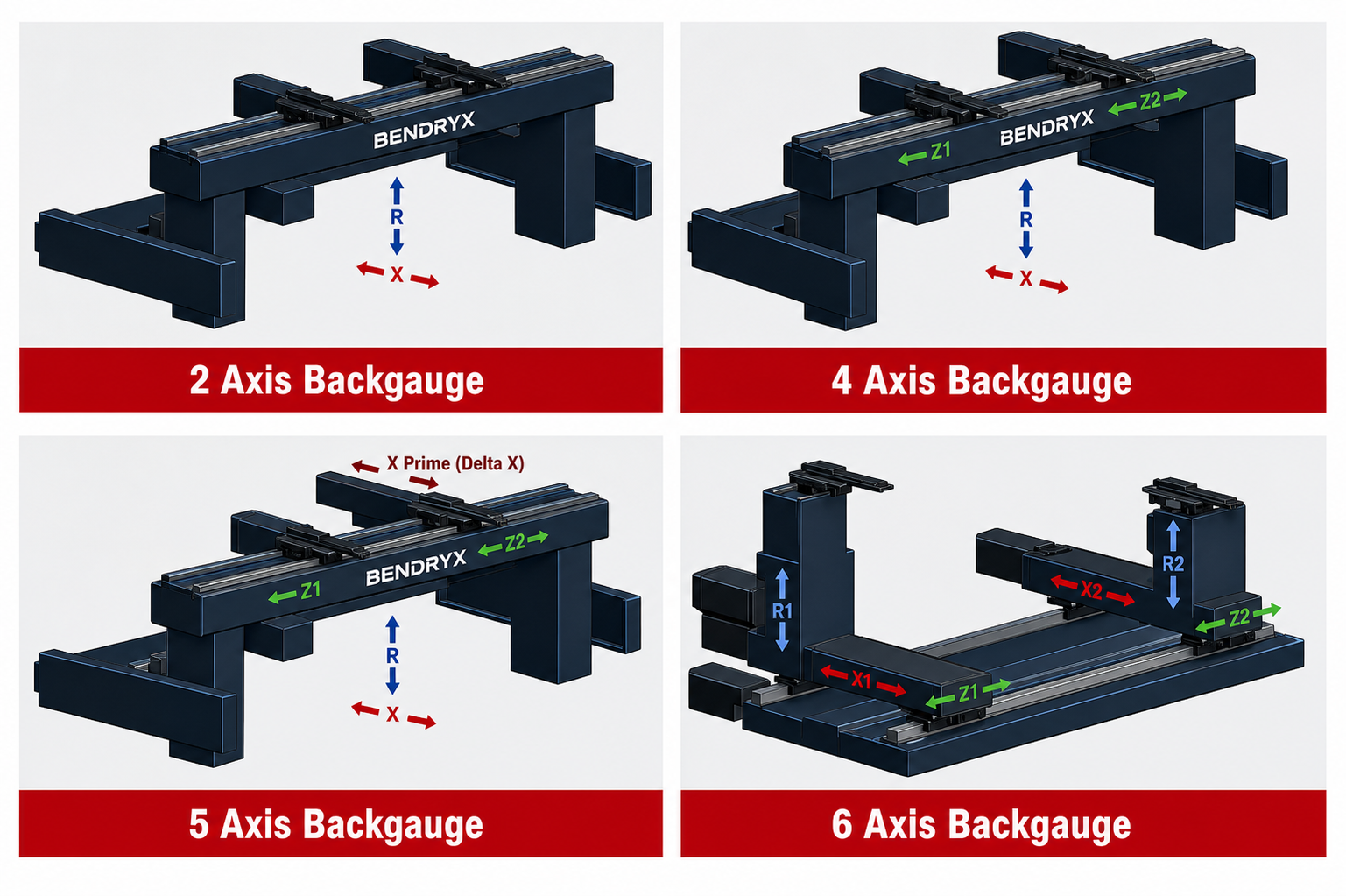
For a typical synchronized down-acting press brake, Y1 and Y2 describe the two controlled ram positions. X describes rear-gauge depth; R describes height; Z1 and Z2 position fingers along the working length. Independent depth and height layouts may use X1/X2 and R1/R2. Manufacturers can use different names, so confirm the actual motion rather than interpreting a letter alone.
Our backgauge guide explains those directions. This article answers the next question: can the quoted CNC, rack, drives and software operate the specified arrangement?
Build a simple axis budget
The following examples are planning arithmetic for a machine with independently controlled Y1/Y2. They are not a statement that every drive architecture uses the same channel allocation.
| Rear-gauge package | Named rear motions | Including Y1 and Y2 |
|---|---|---|
| Two-axis gauge | X, R | 4 named motion channels |
| Four-axis gauge | X, R, Z1, Z2 | 6 named motion channels |
| Six-axis gauge | X1, X2, R1, R2, Z1, Z2 | 8 named motion channels |
Crowning, sheet followers, extra fingers and automation interfaces need their own integration review. Some functions use a positioning channel; others use a different interface. Do not automatically count every accessory as one axis—or assume it consumes no capacity.
What this means for ESA S840 W
ESA’s 2024 bending brochure lists S840 W with four axes as standard and up to six as an option. Therefore, the eight-motion example above cannot simply be promised under that six-axis specification. This is an application-level inference from the brochure, not an ESA-approved wiring design. Check the manufacturer’s model table.
For BENDRYX, S840 W is the starting control platform on applicable configurations. A requested independent six-axis rear gauge needs a suitable control and integration review. A larger display alone does not resolve capacity: the selected rack, software, installed hardware and approved configuration must agree.
Ask the supplier to write the controller variant and enabled functions on the quotation. “ESA control” is not specific enough to establish the delivered package.
Choose motions around the part family
Consider an enclosure with several return flanges. Your discussion should cover where it can be located after each bend, whether the fingers need different lateral positions and whether previously formed features obstruct contact. The answer may be a different finger arrangement or tool setup—not automatically the largest gauge package.
For mixed short parts, ask for a review of finger spacing and available travel. For offset or complex geometry, discuss independent positioning with representative drawings. Treat these as application questions; no single axis count proves that a part is accessible, repeatable or safe to handle.
- Bring the most difficult geometry, not only a simple demonstration part.
- Identify which bends need a different contact surface.
- Ask which motions are programmable and which adjustments remain manual.
- Define the approved handling arrangement and any tooling clearance constraints.
Put the complete arrangement in the quotation
A useful configuration record includes machine model, CNC variant, rack and software scope, named axes, travel ranges, finger arrangement and all proposed accessories. Record what is included now and what would require hardware or licensing later. Avoid a generic promise that a machine is “upgrade-ready.”
Use the BENDRYX configurator as a starting brief, then request an application review for the selected machine. For customers in Canada and the United States, the same principle applies: order an agreed configuration, not an ambiguous axis label.
Bottom line: compare motions and usable working geometry before comparing numbers. A written CNC/gauge schedule makes quotations easier to compare and reduces uncertainty before the machine is built.
Put the guide to work
Build the right package around your parts.
Share your drawing, material, tooling and production requirements. BENDRYX helps customers in Canada and the United States define a machine-specific scope before ordering.
Review my CNC and backgauge package →Technical references are linked beside the relevant discussion. Examples and checklists are BENDRYX planning guidance, not manufacturer-approved settings or performance guarantees. Product information reviewed September 29, 2026; the final signed technical schedule takes precedence.