Bend depth
Moves the gauge fingers toward or away from the tooling to establish flange depth.
Positioning systems explained
A press brake backgauge turns a bend program into repeatable part positioning. Compare the movement, independence and part geometry supported by each BENDRYX package.
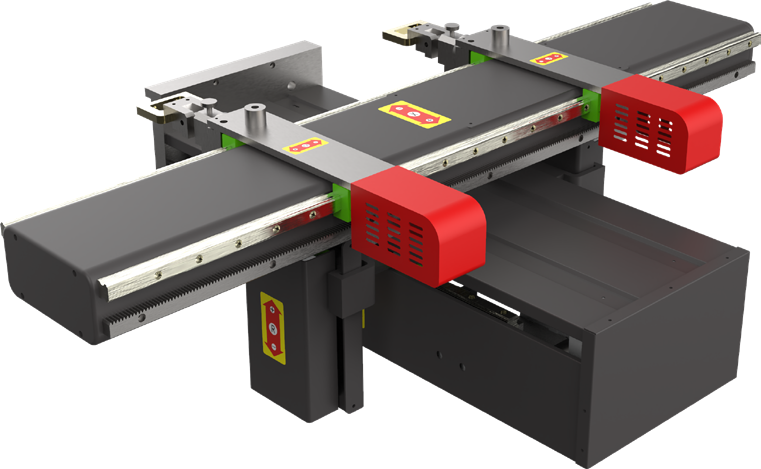
Backgauge systems at a glance
The correct system is the simplest configuration that positions every flange, profile and offset in the intended part family.
Axis terminology
Axis names describe direction and independence. Y1 and Y2 are included for context, but they control the ram rather than the rear gauge.
Moves the gauge fingers toward or away from the tooling to establish flange depth.
Raises or lowers the gauge beam or fingers for changing flange heights and formed features.
Moves the left finger along the working length for width and off-centre setups.
Moves the right finger independently for asymmetric and narrow part setups.
Controls left and right depth separately for tapered flanges and non-parallel edges.
Controls left and right height separately for complex profiles and uneven support points.
Controls the left side of the upper beam. It is a synchronization axis, not a rear-gauge movement.
Controls the right side of the upper beam and works with Y1 to maintain ram position.
May identify crowning, a sheet follower or another controlled function confirmed in the final specification.
Configuration levels
The right package is the simplest system that reliably positions the actual part family.
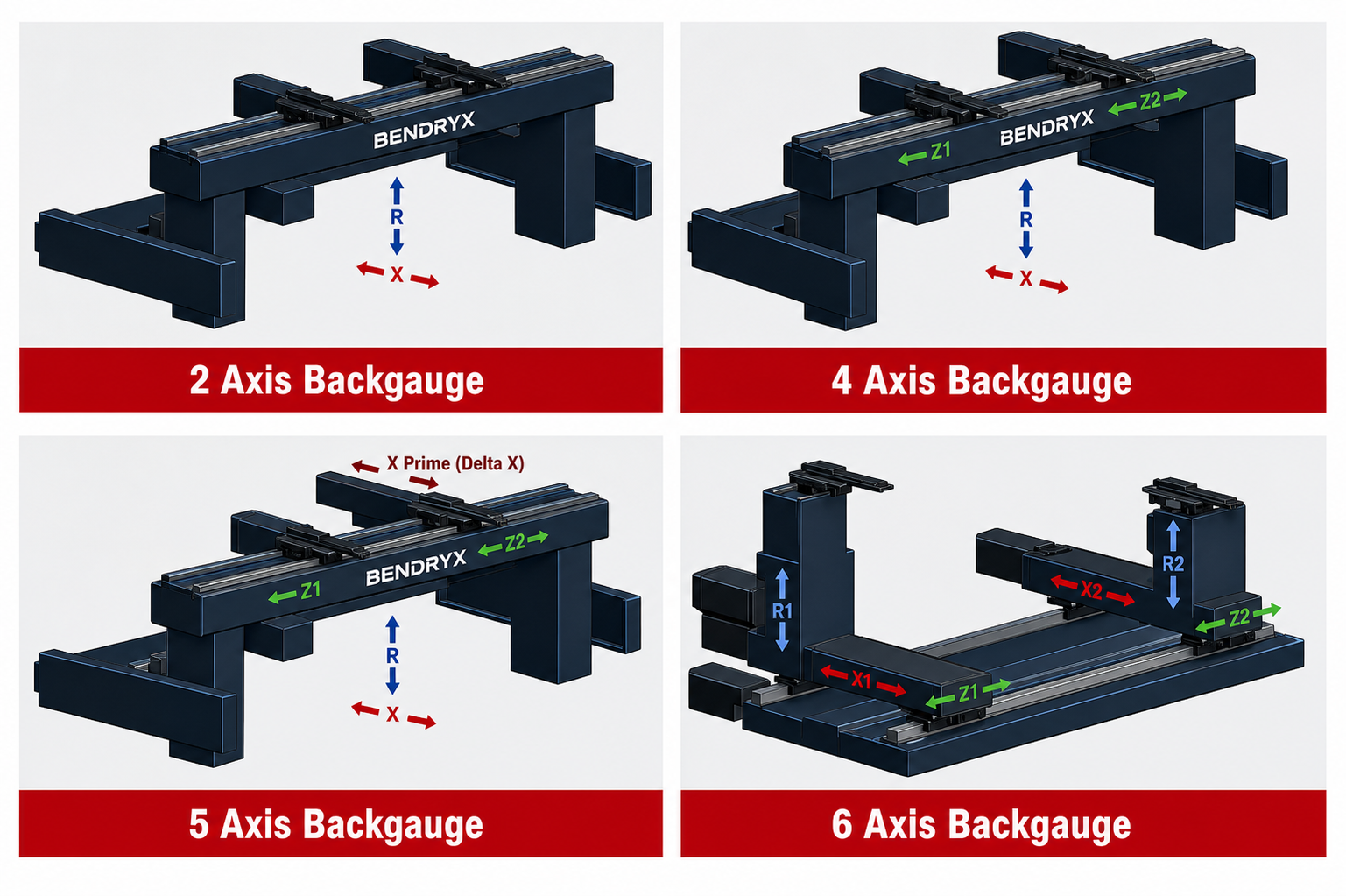
Basic automatic flange-depth positioning.
Adds vertical positioning for changing flange heights.
Adds linked lateral positioning or an application-specific channel.
A versatile package with independent finger placement.
Adds an offset or depth channel for more complex geometry.
Independent left and right depth, height and lateral positioning.
BENDRYX structures
Servo motors, precision ball screws and linear guides support fast movement and repeatable positioning.
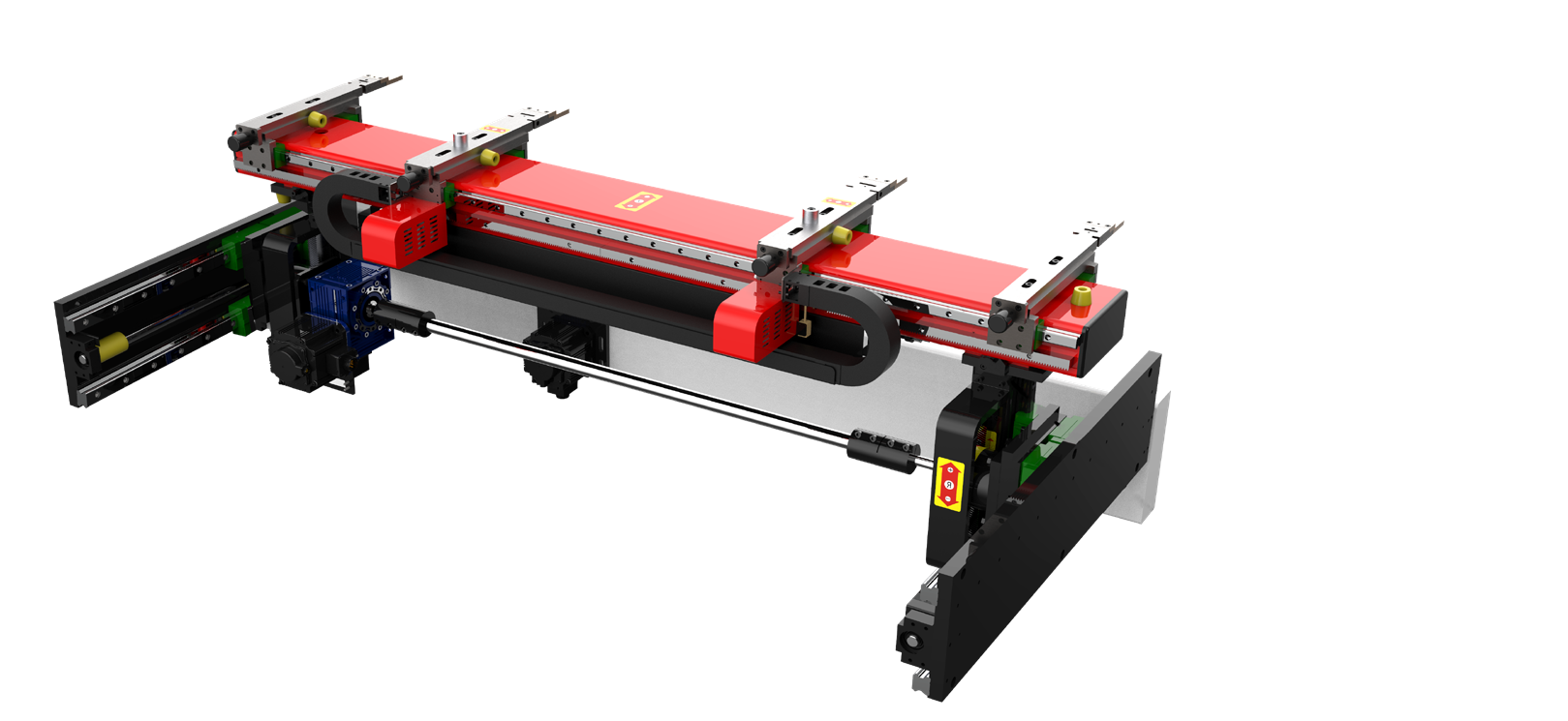
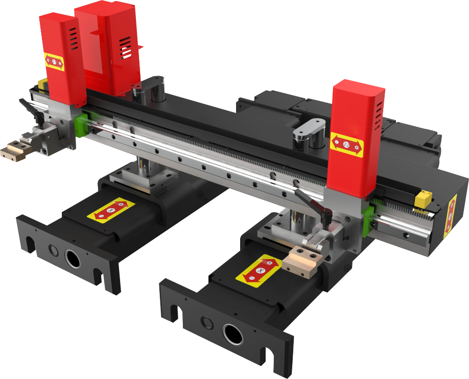
Important: Axis labels can vary by controller and machine architecture. The final BENDRYX quotation confirms every controlled movement and travel.
How to select
Four practical questions usually determine the correct gauge architecture.
Tapered or non-parallel edges may require independent X1 and X2 depth positioning.
Formed features and variable support points benefit from R or independent R1/R2 control.
Z1 and Z2 reduce manual finger repositioning as part widths change.
Long, heavy or flexible parts may also need sheet followers, front supports or automation.
BENDRYX will recommend the BENDRYX rear-gauge axes, ESA control, tooling and support equipment needed for the application.