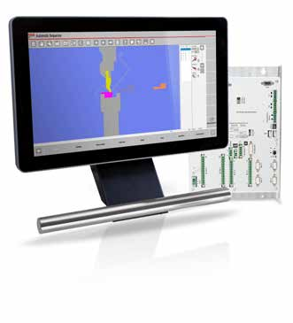
Keep one traceable record linking the drawing revision, tools, material, program and accepted measurements. The CNC screen is only one part of that record.
Planning guidance for buyers and trained teams. Follow the supplied machine and tooling manuals, approved procedures and safeguarding requirements. This is not an operating or commissioning manual.
Identify the job before reviewing the setup
This ESA S840 W first-part checklist is a documentation aid for trained teams. It does not tell an operator how to run a machine or which correction value to enter. Its purpose is to prevent a familiar mistake: approving a good-looking sample without being able to identify exactly what produced it.
Start with the part number and drawing revision. Add the material specification, measured thickness, machine identifier and the program revision intended for the job. Decide which dimensions are critical and how they will be measured before evaluating a trial part.
In the reference program-list screen, the highlighted record and its summary should be treated as information to verify—not authorization to start a cycle.
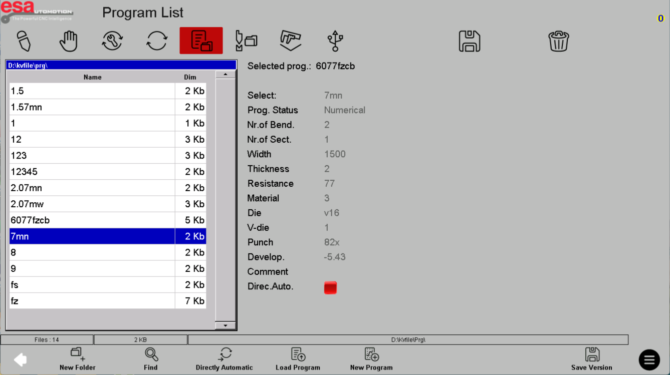
Look for: the selected program, its directory and the job summary. Compare these with the controlled drawing and job record; do not copy example values.
Match the digital tool record to the physical setup
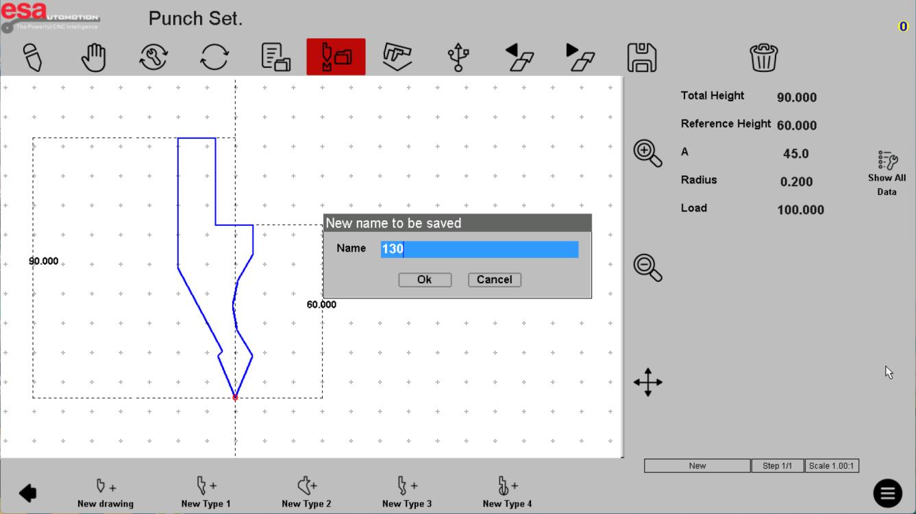
A familiar tool name is not proof that the physical punch or die matches the selected library entry. Record the actual tool identifiers, relevant geometry, station arrangement and clamping interface using the approved setup procedure. Have suitability and load limits reviewed for the complete arrangement.
The tool-setup lesson shows how a tool record is represented. Use it to understand which information needs confirmation, not as a generic instruction to create or modify tooling data on an installed machine.
Also record the blank revision. If cutting and bending are separate departments, make the handover explicit: the programmer and operator need to know which blank definition belongs to this job. See the laser-to-bending workflow guide.
Separate programmed targets from measured results
After the trial part has been produced and made safe to inspect under the approved machine procedure, measure the features required by the drawing and inspection plan. Record actual values with units and the measuring method. Do not replace measurements with a simple “looks good” note.
A programmed target, an axis reading and a correction field represent different information. None is a substitute for inspecting the finished part. The reference editor below helps illustrate that distinction without prescribing operating settings.
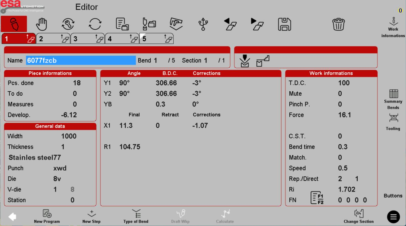
Look for: the active bend tab, material and tool records, and the labels on target and correction columns. Use the installed-system manual to interpret them.
If the part fails inspection, keep the trial record. A qualified review should establish whether the concern involves the drawing, blank, setup, material or another cause before a change is authorized. Never bypass a guard or alter protected settings to complete a trial.
Use a compact first-part release record
| Record | Include |
|---|---|
| Identity | Part, drawing revision, blank revision, machine and program version |
| Material | Grade, thickness, batch reference and finish requirements |
| Setup | Tool IDs, approved arrangement, gauging and handling reference |
| Inspection | Required angles, dimensions, tolerances, actual results and units |
| Changes | Reason, authorized revision and the results of the subsequent check |
| Release | Person responsible, date, accepted program and job-record location |
For a long part, the inspection plan may require measurements at more than one position. Do not choose locations solely because they are convenient. The drawing and your quality requirements determine what evidence is needed.
This record supports traceability; it is not certification of the machine, the process or every part in a batch. Maintain the ongoing inspection checks required by your shop and customer.
Preserve the approved revision for the next operator
Keep the released program distinguishable from a working copy. Save the inspection result and setup record where the next operator can find them. A USB file alone does not preserve the physical tool arrangement or the reason for a previous correction.
Use the backup procedure documented for your controller. If a program is moved to another press brake, confirm compatibility before use; do not transfer protected machine parameters as though they were ordinary job files. The S840 backup lesson explains the difference between record management and production approval.
A repeatable handover answers three questions: which revision is approved, what setup produced it, and what was actually measured? BENDRYX can include those questions in a discussion of the machine, control package and training scope.
Put the guide to work
Build the right package around your parts.
Share your drawing, material, tooling and production requirements. BENDRYX helps customers in Canada and the United States define a machine-specific scope before ordering.
Review my application and training needs →Technical references are linked beside the relevant discussion. Examples and checklists are BENDRYX planning guidance, not manufacturer-approved settings or performance guarantees. Product information reviewed September 29, 2026; the final signed technical schedule takes precedence.